


Optimizing motor selection for motion control applications can have significant performance, cost and maintenance benefits. Select too large a motor and you could overwhelm your actuators and incur unnecessary equipment and energy costs. Select too small a motor and you may not achieve the torque and speed you need for effective performance.
The first thing to note about motor selection is that it is initially not about the motor. Thinking about whether you need a servo or stepper motor, DC or AC synchronous or some other type of motor without detailing your application requirements can be a wasted exercise or could lock you into one type or another, limiting your options for cost and performance optimization.
Start with the application
Typical motion applications include belt-driven conveyors, index tables or rotary devices, robotic arms, gates, and automated guided vehicles. Whatever your application, before you start looking through motor specs, you must determine the load on all axes, the degree of precision you require and amount of control you need over the process. Every mechanism is a little bit different, and there are a wide variety of ways to calculate the motor requirements. Hand calculations are good for simple systems and most manufacturers provide motor sizing tools for their various products.
Another critical parameter is the amount of available bus voltage. Voltage correlates with high speed and lower machine cycle time. If your application calls for more speed than your available voltage can support, you will need a different winding and rotor configuration.
Other factors that should be addressed early in the selection process are the location of the motors and the expertise available to make and implement the selection. Location is critical because installation in dirty or extreme temperatures will negatively impact ultimate performance and drive up maintenance costs. Having the right expertise available is important because, if you do need outside assistance, the later you bring it into the process, the more costly it will be and the more cycles you will have spent up to that point. By and large, however, motor selection is a straightforward process, and reviewing the rest of this article will help you determine what expertise you need. Turning to the motor Once application requirements for load, precision, voltage and other variables have been determined, attention can turn to identifying the motor speed, torque and inertia you will need to meet them. Figure 1 shows the relationship between torque and speed of a servo motor. The motor must have the right speed and torque to hit the operating point defined by your control requirements. If your application requires movement at speed X with Y torque, the average of the maximum and minimum operating points must fall within the continuous duty curve specified by the motor manufacturer.
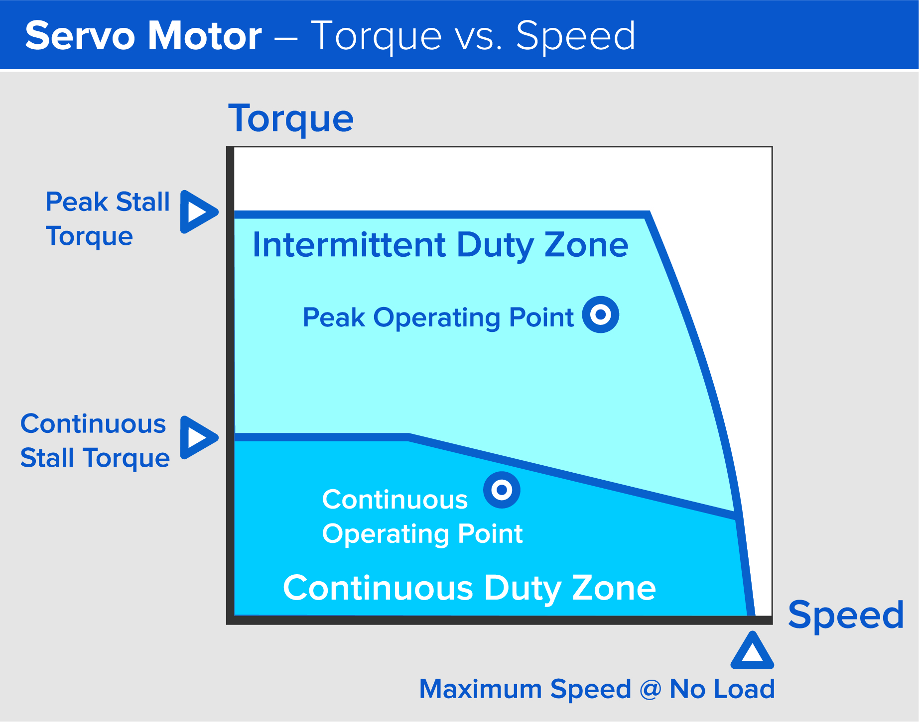
Figure 1: Servo motor torque vs. speed. The average of the maximum and minimum operating points must fall within the continuous duty curve specified by the motor manufacturer. Image courtesy of Thomson Industries, Inc.
The speed, torque and voltage relationship is similar for stepper motors (Figure 2) although you should be more conservative in designating operating points. As a general rule of thumb, the operating range of a stepper should be about half of the max of the speed and torque to ensure that you don’t jeopardize accuracy by missing steps. This is much different than with servos, which you can push more closely to the limits of their operating range. This is because servos rely on closed feedback loops that monitor the motor position against its target position and make constant course corrections. With most steppers in use today, there is no feedback on missed steps, which presents more of a safety risk. Some of the newer stepper motors and related drives, however, have built-in feedback control or other means of detecting missed steps. These are gaining popularity in recent years with more companies offering matched motors and drives that deliver excellent positional accuracy with most of the speed of a brushless servo motor. (Figure 3)
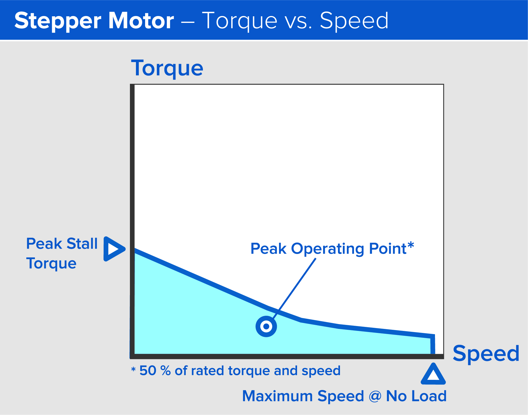
Figure 2: Torque vs speed - stepper motors. The operating range of a stepper should be about half of the max of the speed and torque. Image courtesy of Thomson Industries, Inc.
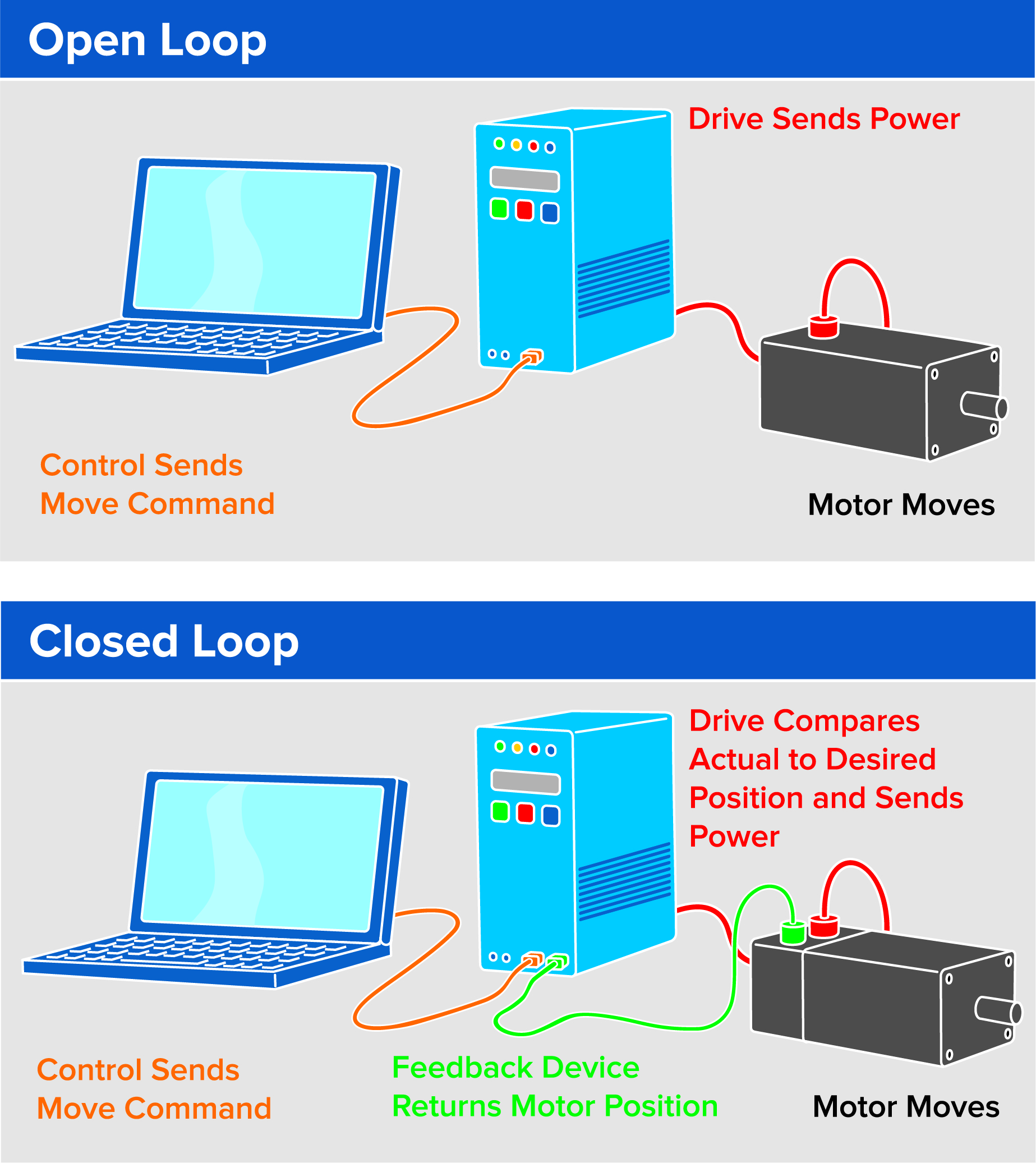
Figure 3: Many of today’s motors rely on closed feedback loops that monitor the motor position against its target position and make constant course corrections. Image courtesy of Thomson Industries, Inc.
The all-critical inertia ratio
Once you have established the speed and torque characteristics, the sizing process is not complete until you match the inertia of the load and motor. The inertia of the load is its weight in kilograms per meter squared. The inertia of the motor is a little more complicated in that it involves both the rotor and the shaft, but, fortunately, motor manufacturers will supply that number. If the ratio of load inertia to the motor is too large, say more than 10 or 20 to 1, the load drives the motor instead of the motor driving the load.
Poor inertia ratio is a common problem in motor selection. While it is generally a good practice to seek the smallest-sized motor possible, focusing only on motor speed and torque without proper attention to inertia can cause major problems. A servo system may not have the characteristic snappy response you would expect. It could overshoot its position target and then return with too much force, wobbling undesirably as it tries to fix on its final position.
On the other hand, picking too large a motor with too much inertia would give you that snappy response but with great inefficiency. You would be devoting much of your energy to spinning up and stopping the motor itself, rather than applying that energy to moving the system load. And selecting a motor that is too large also reduces the overall machine efficiency and raises operating costs. The larger the motor, the higher cost for breakers, cables and other support infrastructure, and this can cascade upwards throughout the application design.
As an example, consider a multi-axis system with an XYZ gantry. If you put too large a motor on the first axis, and it is a carry-to-carry axis, you are just adding more mass that must be carried to the other two axes. This means that the whole gantry system must be bigger to support it.
A precise measurement of inertia is also necessary to determine whether other aspects of the drive system will benefit from simple changes. Instead of selecting a motor with higher inertia, which is physically larger and more expensive, reducing the lead of the drive screw, pitch of the belt or a higher gear ratio may help. These changes reduce the system inertia seen by the motor. This is analogous to pushing on a door at the handle rather than pushing on it beside the hinge.
Belt-driven systems are optimal for high speed but often require gearing for good motor matches. Each revolution of the input shaft produces much greater output than a single rotation of a ball screw. Where the typical pitch on a belt-driven system, for example, might be 150 mm, a comparable ball screw pitch might be only in the 5 mm to 25 mm range. The smaller the distance the mechanism moves for each motor turn, the less inertia the motor sees through the mechanism, and the less likely is the need for gearheads to achieve a more favorable ratio, according to the following equation:
Inertia ratio with gearhead = Inertia Ratio without gearhead / gearhead Ratio^2
An accurate calculation of the inertia of each component is key to selecting the right motor or motor and gearhead combination.
Online product tools can also assist with the selection of the right motor. For example, Thomson Industries designed LinearMotioneering®, an online tool that facilitates fast and easy linear motion system sizing and selection, enables accurate motor sizing mounting and features advanced ordering technology.
Smarter and more efficient motors
Of course, motion control technology itself has not been sitting still. Advances in motor efficiency and electronics improve selection and may compensate for match discrepancies to some extent. Where 10 or 15 years ago, we might be shooting for a 5 or 10 to 1 reflected inertia ratio, with today’s more advanced drives, we can get closer to 25 or 30 to 1. This is thanks to the high speed of the drives and feedback devices which make fine adjustments quicker than previous drives could do. We can now get more work done with a smaller, more compact motor, which is worth keeping in mind when replacing motors. Many people still replace same with same without looking into the benefits that new technology can deliver.
Some modern actuators, for example, come integrated with pre-mounted and pre-tested servo motors. These have a drive built into the rear housing or otherwise attached to the motor itself. They offer most of the performance of a full servo system, although restricted bus voltages may limit speed a little. Integrated servo motors eliminate some cabling and simplify setup, making it much easier for technicians new to servos to get a system up and running sooner.
Recent advancements in drive and motor technology are bringing brushless motor performance to linear actuators at a significantly lower price than was previously possible. These new actuators offer higher speeds, longer life and less maintenance as well as the ability to recover energy from helping loads to recharge system batteries. While these actuators may not have the same closed loop positional accuracy as traditional servo motor actuators, they do offer better control than comparable hydraulic systems – and with fewer parts and overall lower system costs. (Figure 4)
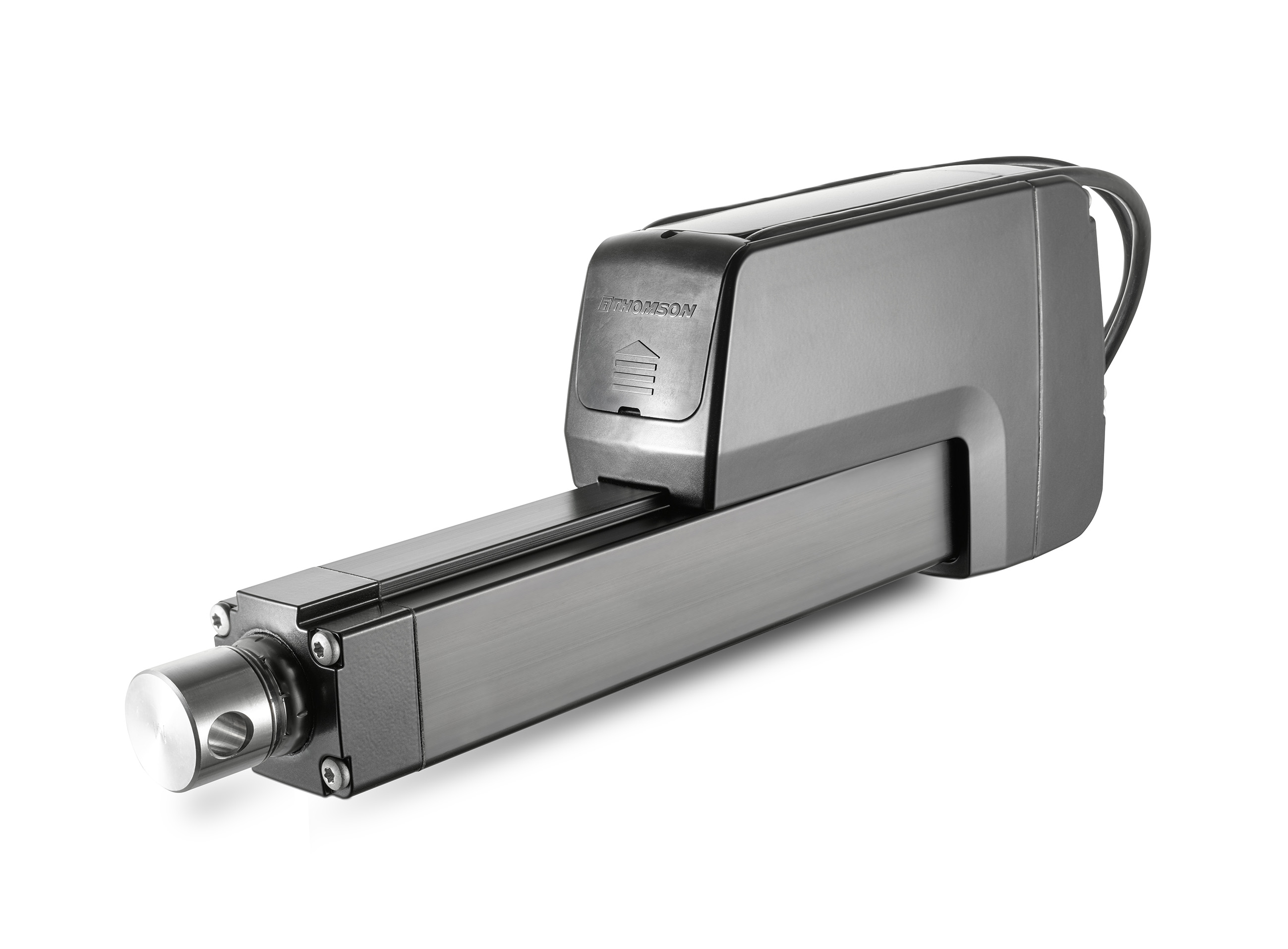
Figure 4: Electric linear actuators using brushless motors, which offer higher speeds, longer life and less maintenance, are becoming more common and affordable. Image courtesy of Thomson Industries, Inc.
Pairing the motor selection and the actuator selection also simplifies the ordering process; reduces the need for additional after-installation validation; increases reliability; and simplifies maintenance, reducing the total cost of owning and operating an actuator system. Because pre-mounted servo motors must be limited in size, they may not be appropriate for applications requiring larger systems. Although precision linear actuators with integrated servo motors do tend to be on the smaller side, large actuators with integrated large servo motors are available.
The next wave
As motor system technology advances, it will play an increasingly important role in manufacturing strategies. Modern drives will likely have internet connectivity and communicate with popular communications interfaces and protocols such as Ethernet, ProfiBus and CAN bus. Motors will be more accessible and configurable across plant networks, making it easier to control and configure existing applications, while delivering visualization that could suggest new productivity and cost-saving applications.